Spain
Ruleset
For the Spanish market, we calculate the access capacity according to 'Boletín oficial del estado Nr. 131' published by the CNMC on June 2nd 2021.
The access capacity is limited by a set of rules, each rule can be enabled or disabled individually in the calculation options.
Power
We restrict the power according to the following table. The maximum power limit is enforced, if a power is higher than the maximum. The minimum power limit is only used for logging purposes, if the power is lower than the minimum, a warning message is logged for the user but the limit is not applied.
For singular requests (load requests on medium voltage or high voltage buses), the maximum power limit is further reduced to 20% of the table value when stricter limits are enabled.
| Voltage from [kV] | Min. power [MW] | Max. power [MW] |
|---|---|---|
| 0 | 0 | 0.1 |
| 1 | 4 | 10 |
| 17.5 | 4 | 15 |
| 22.5 | 4 | 20 |
| 27.5 | 4 | 30 |
| 37.5 | 4 | 40 |
| 47.5 | 5 | 50 |
| 60.5 | 6 | 60 |
| 88 | 10 | 100 |
Example
Applying this rule to an 11kV-bus would match the 1kV entry (highest matching voltage level) and...
- log a warning message if the access capacity is less than 4MW (minimum limit), but not enforce it
- not affect the access capacity if the access capacity is limited from other rules to a value between 4MW and 10MW
- reduce the access capacity to 10MW if other rules would allow an access capacity higher than 10MW
- reduce the maximum to 2MW (20% of 10MW) if this is a singular request and stricter limits are enabled
Voltage Change
We limit the voltage change caused by the additional generation to 3% for < 36kV and 2.5% for >=36kV buses in a full load and full generation loading of the grid. This rule applies to all buses except for busbars. For busbar, see Voltage Change At Bus Bars criterion below.
Example
Calculation of access capacity at bus highlighted by red arrow 
- Power flow with 100% load, 90% generation, 0% additional generation ➔ 1.033 pu
- Power flow with 100% load, 90% generation, 100% additional generation ➔ 1.127 pu
- Calculate voltage change: (1.127-1.033) / 1.033 = 9.1 %. The calculated voltage change (9.1%) is higher than the limit (3%), therefore Adaptricity will lower the attempted additional generation until the limit is satisfied. This lower value is shown as access capacity.
Voltage Change At Bus Bars
We limit the voltage change at busbars caused by all generation to 5.5% for < 36kV and 4% for >=36kV buses. Unlike the regular voltage change, the voltage change at busbars considers the cumulative voltage change including existing generators installed at the busbar.
Details
We consider a generator to be installed at a bus bar if it's connected to...
- a bus of type "BUS_BAR"
- or a lower voltage bus of a transformer
- or a bus, that is connected through one or multiple lines or connections with an impedance of less than 1mΩ to a bus fulfilling 1 or 2
Busbars (according to definition of 1 and 2) along with their low-impedance neighbors (3) form a small busbar-"neighborhood", in which all pre-existing generators are switched on at the same time along with the additional generation under investigation. In other words, additional generation must share the tolerated voltage change with existing generators. This is stricter than the regular criteria, where the additional generation can cause the entire tolerated voltage change all by itself. Due to this stricter criterion of how the voltage change is calculated, the limit itself is less strict at busbars (5.5%) than at other buses (3%).
Example
Calculation of access capacity at busbar highlighted by red arrow 
- Power flow with load ON, non-busbar-generation ON, busbar-generation OFF, additional busbar-generation OFF ➔ 0.968 pu
- Power flow with load ON, non-busbar-generation ON, busbar-generation ON, additional busbar-generation ON ➔ 1.063 pu
- Calculate voltage change: (1.063-0.968)/0.968 = 9.8 %. The calculated voltage change (9.8%) is higher than the limit (5.5%), therefore Adaptricity will lower the attempted additional generation until the limit is satisfied. This lower value is shown as access capacity.
Enforce absolute voltage
We ensure the voltage of any bus in the grid remains between 93% and 107% of it's nominal voltage.
Example
In a grid with a nominal voltage of 400V, the voltage at all buses must be at least 372V and not more than 428V.
Fault Power Ratio
We limit the access capacity such that the ratio of short circuit power to operation power doesn't fall below 6 (configurable), i.e. that the equation S3ph > 6* Sop is satisfied. S3ph being the maximum 3-phase maximum short circuit power at bus A and Sop being the sum of all existing apparent nominal generation power at bus A including bus A's access capacity.
This ensures that...
- operational currents can be clearly distinguished from fault currents
- avoid that much power is installed at weak buses (the short circuit power of a bus can be interpreted as indicator of the strength at that location of the grid)
Example
The 3-phase maximum short circuit power at bus A is S3ph = 600kVA. There are two additional generators at the same bus with a rated power of 20kW and 30kW respectively. The access capacity at bus A is therefore limited to 600kVA / 6 - 20kW - 30kW = 50kW.
Line & transformer loading
We limited the line and transformer loading according to the following limits:
| Voltage < 36kV | Voltage ≥ 36kV | |
|---|---|---|
| max Line Loading | 100 % | 110 % |
| max Transformer Loading | 70 % | 120 % |
Line loading at busbars
We apply a different line loading threshold to lines that are directly connected to a busbar. By default, the default line loading is also set to 70%, but can be adjusted by the user. Busbar's are identified as buses with type "BUS_BAR" that are located on the lower voltage side of a transformer, whose lower voltage side is below 36kV. If no bus has type "BUS_BAR", we interpret the bus immediately connected to the transformer as bus bar. All lines leaving a bus identified as bus bar gets the busbar limit (70% by default).
Unavailability in meshed networks
In medium and high voltage grids, we evaluate the access capacity in conditions, where loops are being opened (simulated network outage). More formally, Adaptricity will
- Find all loops that contain at least one bus with a voltage > 1kV (colorized in screenshot)
- For Each loop, the bus closest to the network feeder (black arrow) is found (buses A, B, C, D)
- Each loop is separately opened at both loop-branches closest to the buses found in step 1.
- For each of the opened branches a access capacity calculation with limited* rules is performaned.
- The access capacity of all buses are limited to the lowest value found in any topology * only the line and transformer loading criteria are evaluated.
For performance reasons, the evaluation is limited to 12 alternative topologies apart from the main toplogy, this means that usually two loops can be opened. 
Limit to hosting capacity of overlaying grid
When you calculate the access capacity in a low voltage grid that is linked to a medium voltage grid, Adaptricity tries to use a pre-calculated result of the access capacity in the medium voltage grid at the bus where the low voltage grid is connected and limits the access capacity in the low voltage accordingly. Enabling this rule ensures that the calculated access capacity in the low voltage grid will not cause violations in the medium voltage grid.
Details
The parent grid's result are considered, if all of the following criteria are fulfilled:
- The hosting capacity of the parent grid was calculated without any add-ons.
- The hosting capacity of the parent grid was calculated using exactly the same settings as those currently selected.
- The electrical parameters of the parent grid have not changed since the calculation.
Example
The access capacity in the medium voltage at bus "A" is 200kW. A low voltage grid is connected a bus "A". When calculating the access capacity of low voltage grid the power at every bus in the low voltage grid is restricted to 200kW.
Mesh Classification
Definitions
- Position: A branch coming out of a station.
- Radial: A bus that can be de-energized by disconnecting a branch.
- Simple Meshed: A bus suplied through 2 positions.
- Multi Meshed: A bus suplied through 3 or more positions.
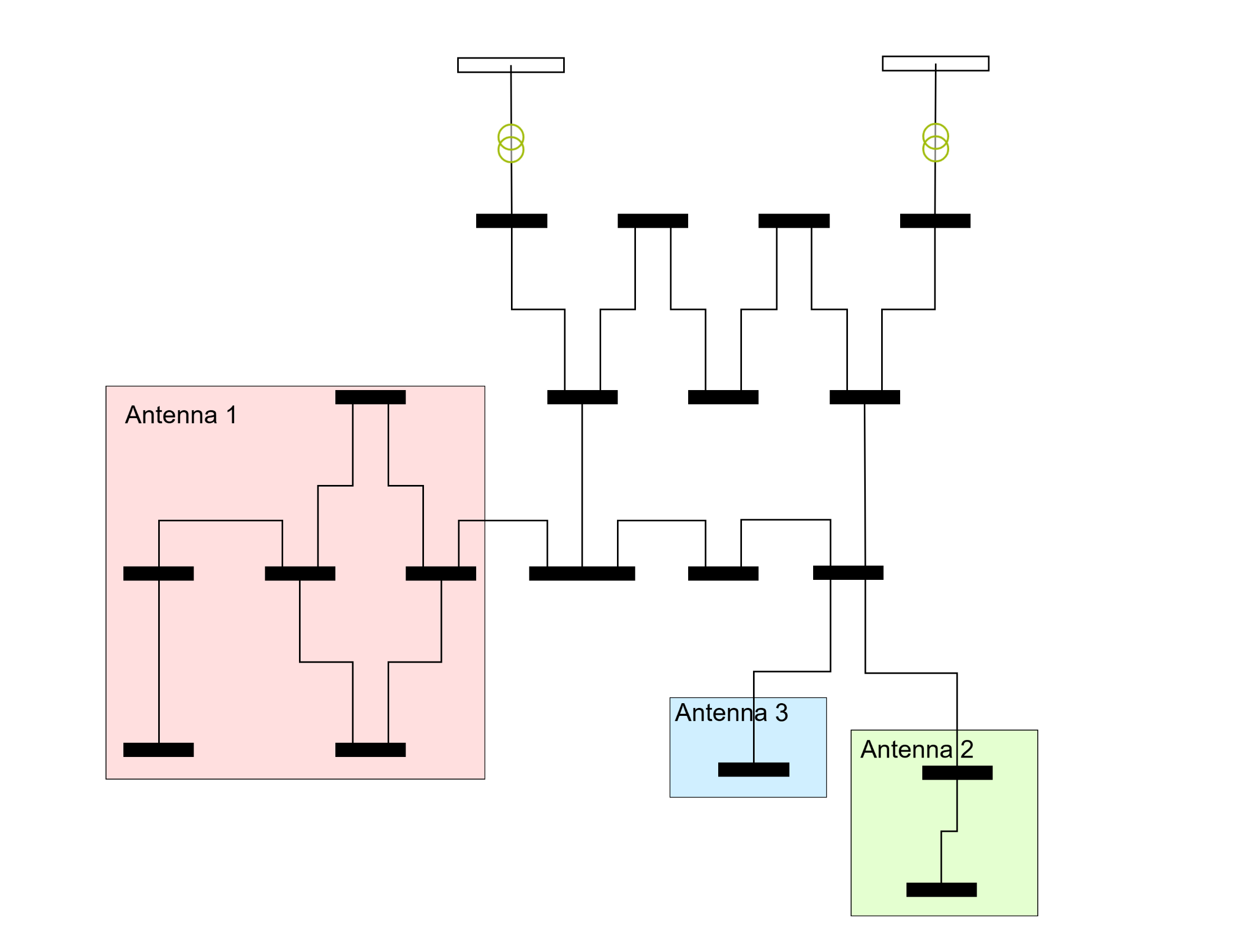
- Antenna: A group of radial buses de-energized by the same branch.
Classifications
Bus is classified as Radial if:
- Is inside a station.
- Is connected to a network feeder inside a station, and, can be de-energized by disconecting one branch.
- Is in a grid that doesn't have any stations (even if the grid has network feeders).
Branch is classified as Radial if:
- Is inside a station.
- At least one bus is radial.
Bus is classified as Simple Meshed if:
- Is suplied through 2 positions.
Branch is classified as Simple Meshed if:
- Both connected buses are simple meshed.
- At least one bus is simple meshed and the other is not radial.
Bus is classified as Multi Meshed if:
- Is suplied through 3 or more positions.
Branch is classified as Multi Meshed if:
- Both connected buses are multi meshed.