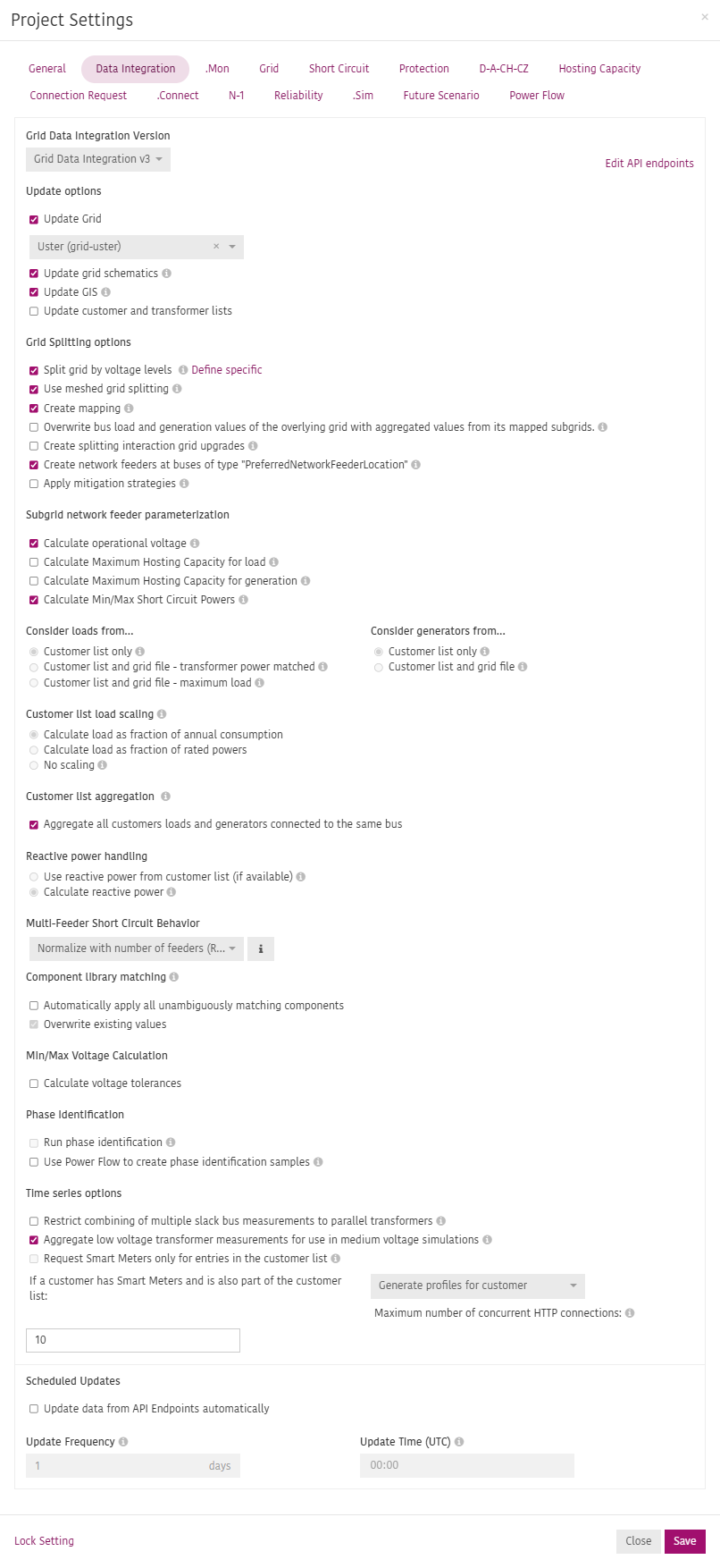
Data Integration
This section defines all API endpoints and settings to automatically import and update grid models, customer lists and time series data.
INFO
Usually this section is configured with the help of an Adaptricity Project Engineer or Developer.
Grid Data Integration Version
Specifies the version of the Data integration API to be used by the system. The API endpoints can be specified by clicking on Edit API endpoints.
Update options
Specify what should be automatically updated.
- Update Grid: select the grid to be imported and updated for this project from the API endpoint.
- Update grid schematics: Shoud the schematic drawing of the grids be updated? If unchecked, existing schmematic element coordinates, bus orientations, bus widths, and selected subgrid colors on transformers will not be overwritten.
- Update GIS: Should GIS coordinates be updated? If unchecked, existing GIS coordinates of grid elements will not be overwritten.
- Update customer and transformer lists: Fetch updated customer and transformer lists from the API if available.
Grid Splitting options
Specify if and how the grid should be split on import.
- Split grid by voltage levels: If checked, the grid is split at specific or all voltages levels. If unchecked the grid will only be split into subgrids if the initial grid consists of multiple islanded grids. Click on
Define specificto specify the voltage levels where splitting should be applied. - Use meshed grid splitting: When enabled, meshed grids will always be split off. The subgrids may contain multiple network feeders.
- Create mapping: When enabled, the split-off subgrids are linked together, i.e., a higher-voltage level grid will receive references to lower-voltage grids in its mapping table. The subgrids are replaced by electrically equivalent loads and generators in the higher-voltage grid.
If the grid being split does not have any consistency errors, the network feeders of the subgrids are automatically parameterized based on the power flow and short circuit computation results on the higher-voltage grid. - Overwrite bus load and generation values of the overlying grid with aggregated values from its mapped subgrids: If checked, during the mapping load and generation values of the subgrids will be aggregated and written into the overlying grid.
- Create splitting interaction grid upgrades: If checked, creates default-on grid upgrades that correct the aggregated load and generation and network feeder parameters to consider all active-on grid add-ons in the project.
- Create network feeders at buses of type PreferredNetworkFeederLocation: In the subgrids created by splitting, this places automatically created network feeders at buses with the special «PreferredNetworkFeederLocation» type.
- Apply mitigation strategies: Mitigation strategies try to correct consistency problems in grids automatically. You can configure the mitigation strategies that will be applied in the Grid tab.
Subgrid network feeder parametrization
Specify how the network feeders in subgrids created from the grid splitting are parametrized.
- Calculate operational voltage: In the subgrids created by splitting, operational voltage is set using the power flow from the higher voltage grid. Check this option if the loads and generation defined in the grid model represent a realistic operation situation. When disabled, the operational voltage will be set to 1.0 p.u. (nominal voltage of the slack bus).
- Calculate Maximum Hosting Capacity for load: When this checkbox is selected, a hosting capacity calculation will be performed across all grids that contain subgrids (typically medium voltage grids). The resulting hosting capacity values will then be applied as the maximum hosting capacity on the network feeders of the associated subgrids (typically low voltage grids). This means that the hosting capacity of the subgrids will be constrained by the maximum hosting capacity of the overlaying grid if the corresponding limit in the hosting capacity settings is selected.
- Calculate Maximum Hosting Capacity for generation: When this checkbox is selected, a hosting capacity calculation will be performed across all grids that contain subgrids (typically medium voltage grids). The resulting hosting capacity values will then be applied as the maximum hosting capacity on the network feeders of the associated subgrids (typically low voltage grids). This means that the hosting capacity of the subgrids will be constrained by the maximum hosting capacity of the overlaying grid if the corresponding limit in the hosting capacity settings is selected.
- Calculate Min/Max Short Circuit Powers: When this checkbox is selected, a short circuit calculation will be performed across all grids that contain subgrids (typically medium voltage grids). The resulting short circuit power will then be applied as the maximum short circuit power on the network feeders of the associated subgrids (typically low voltage grids). This means that the short circuit power of the subgrids will be constrained by the maximum short circuit power of the overlaying grid.
Consider loads from...
Loads can be imported in Adaptricity in two ways - through the grid file and through the customer list. This setting specifies the behaviour of the import.
- Customer list only: Loads from the customer list are imported into the grid model. Loads defined in the grid file are ignored.
- Customer list and grid file - transformer power matched: Loads both from the customer list and from the grid file are imported into the grid model. The power of the loads from the grid file are subtracted from the transformer measurement and the remaining power is distributed among the loads defined in the customer list.
- Customer list and grid file - maximum load: Loads both from the customer list and from the grid file are imported into the grid model. The resulting power in the grid model is the sum of the transformer measurement plus the sum of the loads defined in the grid file. The option leads to the overall largest load in the grid model.
Consider generators from...
Generators can be imported in Adaptricity in two ways - through the grid file and through the customer list. This setting specifies the behaviour of the import.
- Customer list only: Generators from the customer list are imported into the grid model. Generators defined in the grid file are ignored.
- Customer list and grid file: Generators both from the customer list and the grid file are imported into the grid model.
Customer list load scaling
Specifies how the load data from the customer list should be scaled.
- Calculate load as fraction of annual consumption: The optimization algorithm assigns an apparent power to loads based on the share of load energy with respect to the total load energy.
- Calculate load as fraction of rated powers: The optimization algorithm assigns an apparent power to loads based on the share of load power with respect to the total load power.
- No scaling: Use the active and reactive power defined in the customer list without scaling. If no reactive power is defined, a default reactive power characteristic of cos(ϕ)=1 is used.
Customer list aggregation
- Aggregate all customers loads and generators connected to the same bus: When checked, loads and generators hosted by the same bus are merged into one load/generator element, thus resulting in less grid elements but lowering the data resolution about single customers.
Reactive power handling
Specifies how reactive power should be added to loads and generators from the customer list.
- Use reactive power from customer list (if available): Use the reactive power defined in the customer list (supported as of protocol version v2.1). If no reactive power is defined in the customer list, a default reactive power characteristic of cos(ϕ)=1 is used.
- Calculate reactive power: The reactive power is calculated from the active power based on the transformers’ cos(ϕ) defined in the transformer list.
Multi-Feeder Short Circuit Behavior
Defines how the short circuit powers of network feeders are calculated in meshed grids created by the meshed grid splitting. These grids might be fed by more than one network feeder.
Normalize with number of feeders (Recommended)
The calculated short circuit power in the unsplit grid is divided by the number of connections to the subgrid. Choose this if the feeders are electrically close to each other (e.g. in case of parallel transformers).
Example:
A medium and low voltage grid are interconnected at buses A and B. In the medium voltage grid, buses A and B each have a short circuit power of 10 MVA. In the low voltage grid, feeders at A and B are created with a power of 5 MVA (10 MVA / 2). A short circuit at a bus connected losslessly to both feeders has a short circuit power of 10 MVA (5 MVA + 5 MVA).
Full power at all feeders
The calculated short circuit power in the unsplit grid is fully applied to each feeder in the subgrid. Choose this, if all feed-in points can provide the full short circuit power at the same time. This is rarely the case in reality and typically leads to unrealistically high power compared to the other option.
Example:
A medium and low voltage grid are interconnected at buses A and B. In the medium voltage grid, buses A and B each have a short circuit power of 10 MVA. In the low voltage grid, feeders at A and B are created with a power of 10 MVA. A short circuit at a bus connected losslessly to both feeders has a short circuit power of 20 MVA (10 MVA + 10 MVA).
Component library matching
Specifies how entries in the team-wide component library are applied to the relevant grid elements.
- Automatically apply all unambiguously matching components: Apply the component library to all grid elements where there is an unambiguous match.
- Overwrite existing values: If electrical parametrs for grid elements are already present in the grid file, should they be overwritten by values in the component library?
Min/Max Voltage Calculation
Specifies the worst case scenarios or load situations that lead to the minimum and maximum expected voltages in a grid and saves the calculated voltage as a grid attribute. The parameters are used when selecting Check voltage violations in sibling grids in certain calculations.
- Calculate voltage tolerances: Check, if the min/max voltage calculation should be executed.
- Apply active grid upgrades and connection requests: Should active grid upgrades and connection requests be applied when calculating the voltage tolerances?
Phase Identification
In case of grids with unbalanced load and generator data and unknown phase affiliation, specify if a phase identification algorithm should be run to assign the phase belonging.
- Run phase identification: Train phase identification AI models after a data update.
- Use Power Flow to create phase identification samples: Using power flows to calculate transformer powers to create phase identification samples will increase the accuracy, but it will also massively increase the computation time. If unticked, the transformer powers will be calculated ignoring grid losses.
Time series options
Specify how time series data should be imported.
- Restrict combining of multiple slack bus measurements to parallel transformers: If restricted to parallel transformers, each of the transformers must have the same start and end buses.
- Aggregate low voltage transformer measurements for use in medium voltage simulations: When enabled, transformer measurements in lower-level grids (e.g., low voltage grids) are aggregated to input time series for simulations in the upper-level grids (e.g., medium voltage grids). Activate this if you do not have measurements capturing the total power below a transformer. If the power consumed by transformer circuits is measured, deactivate this option. Note: This setting only has an effect if .Mon is enabled in the project.
- Request Smart Meters only for entries in the customer list: Limit the requests for Smart Meters to the buses from the customer list.
- Maximum number of concurrent HTTP connections: The maximum number of concurrent HTTP connections that are used to download the time series.
Scheduled Updates
Specifies the update schedule to automatically retrieve new data from the API endpoints.
- Update Frequency: Determines how often the automatic background updater will refresh and download new data. The higest possible frequency is once a day.
- Update Time (UTC): Determines when during the day the automatic background updater will refresh and download new data.