Power Flow Calculation
Run a power flow calculation on a specific grid. The inputs for the power flow calculation in the grid are:
- active and reactive power of the loads and generators
- voltage magnitude and voltage angle at the slack bus
The calculation results are:
- power flow over the transformers, cables and connections
- voltage magnitude and voltage angle at the buses
- current magnitude and current angle at the lines, connections and transformers
- active and reactive power losses at the lines and transformers
- voltage drop over lines, connections and transformers
- loading of fuses
Calculation Options
Click on the button at the top of the page to open the calculation options.
INFO
Changes to the options here will be used for the calculations while you stay on this page. Reloading the page will restore the default options of this project.
- Merge segments: Check this option, if the grid topology should be simplified by merging line segments into single lines.
- Assume different line temperature: Define if the power flow should run with a line temperature that differs from the default line temperature defined in the Project Settings.
Grid
The power flow calculation is run on a single grid at a time. Choose the grid that should be calculated from the Grid dropdown list.
For small grids the power flow calculation starts automatically. The power flow calculation can be started manually by clicking .
Grid Upgrades, Connection Request and Scenarios
Grid Upgrades and Connection Requests are applied to the grid by default depending on their status. They are part of the grid model for the duration of the simulation. The selected Grid Upgrades and Connection Requests are visualized in the grid.
To change the default selection, just select or deselect the desired add-ons from the list. The selection is saved for the duration of the session, even when navigating to other simulations within the Adaptricity software. Reloading the page or clicking on the refresh button will restore the default selection.
Scenarios and Load Situations are never applied by default. They need to be specifically selected.
WARNING
A power flow calculation can only be run if the grid is consistent.
INFO
If any grid upgrades or connection requests cannot be applied to the grid (for example, because a grid element no longer exists), then they are deselected and a warning is shown stating the reasons why they could not be applied.
INFO
In some cases the power flow does not converge.
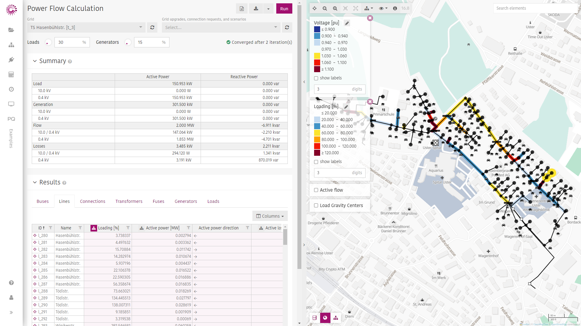
Summary
In this section, a summary of the total installed load and generation in the grid and a summary of the power flow results (flow and losses) grouped by voltage level are shown. Transformers are listed separately with two voltage levels (on the primary and the secondary sides)
Results
The power flow results are visualized in the results table and in the grid viewer. The results can be exported by clicking the download button at the top of the page. A print friendly output can be created by clicking at the top of the page.
Results Table
The power flow results for all elements are shown in the results table, grouped by electrical component. The results in every column can be visualized in the grid viewer by clicking next to the column name.
More columns can be added to the table by clicking on .
TIP
- Sort the table by descending or ascending values by clicking on the column name.
- Filter the table by condition or by specific values by clicking next to the column name.
- Center the grid viewer on an element by clicking on next to the element's ID.
- Multiple columns can be visualized in the grid viewer by keeping CTRL clicked and then clicking .
Grid Viewer
The grid viewer will color the electrical components based on the selection the the results table. A standard color scale will be applied. The scale can be edited by clicking the icon next to the variable name. Clicking on will show the result next to the electrical component.
The direction of the power flow over lines, connections and transformer can be shown by activating .
The will show the geometrical center of the load distribution in the grid.
Clicking on an electrical component in the grid viewer reveals the attributes and the Power Flow Results of that component on the right.