Hosting Capacity
The hosting capacity calculation indicates how much additional load or generation power [kW] can be added to any connection point before reaching the operational limits of the grid.
Calculation
The hosting capacity calculation itertively increases the power of additional load or generation at a bus. At each iteration a Power Flow calculation is run and the operational limits of the electrical components are checked. The hosting capacity of a bus is the additional power that can be added before any of the operational limits are violated. This is repeated for all buses.
Details
Example: assuming the line loading threshold is set to 80%, the hosting capacity of a bus x is 50kW and it is limited by the loading of line y. If you add a generator with 50kW to bus x and run a power flow, the line loading of line y will be 80% (or slightly less, see section convergence threshold.)
INFO
The setpoint of grid controllers such as on-load tap changing transformers, voltage regulators and voltage-dependent reactive power characteristics is computed before the hosting capacity calculation. The state of the controllers in this operating point is used for the subsequent hosting capacity calculation - they are kept constant.
This prevents the additional load/generation from taking up all flexibility provided by the grid controllers.
Settings
Click on at the top of the page to change the settings of the hosting capacity calculation.
The settings are saved for the current calculation. Reloading the page will restore the default settings for this project. Click to run the Hosting Capacity calculation with the current settings.
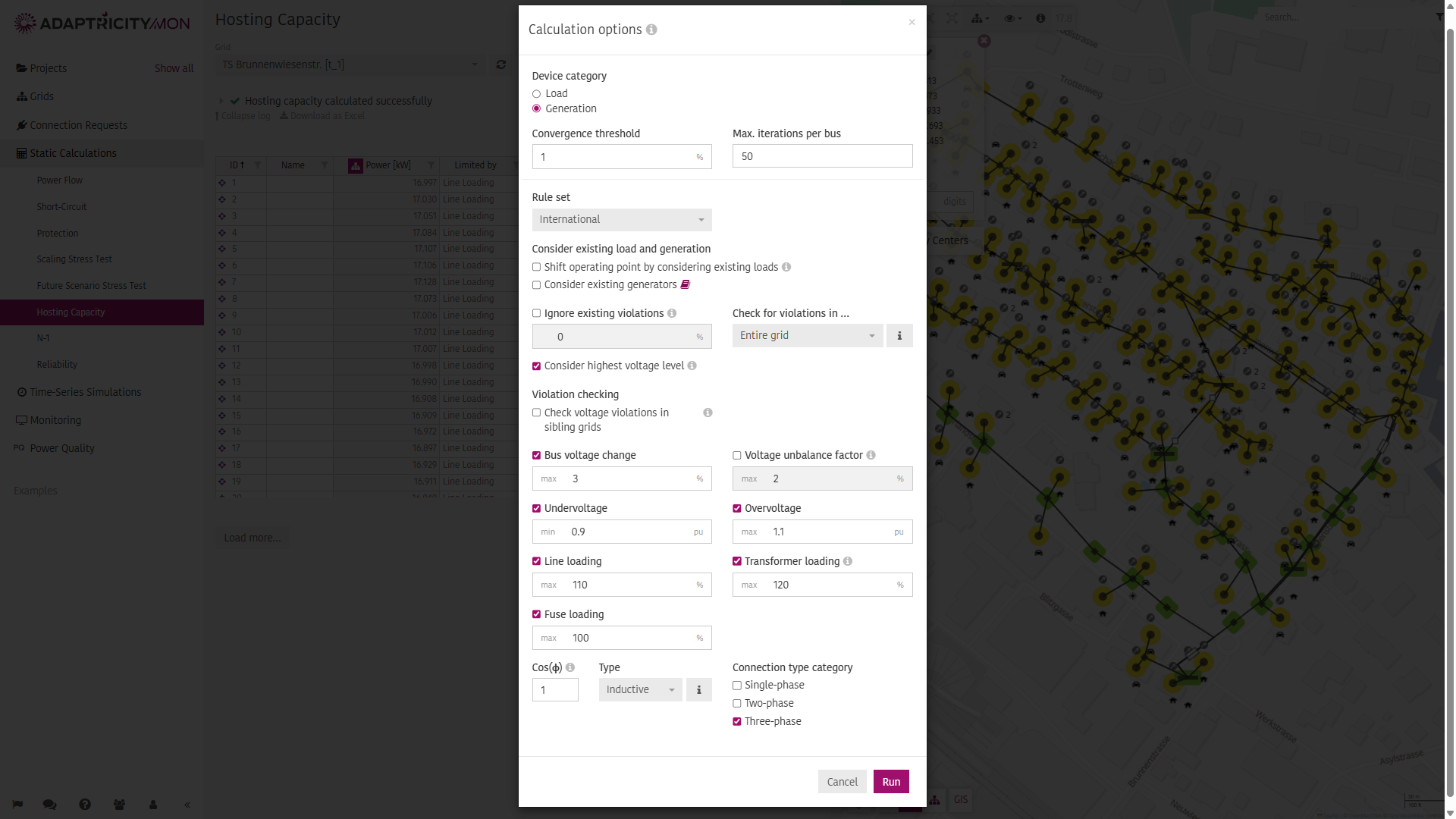
Device Category
Choose which device category should be considered during the hosting capacity calculation:
- Load: evaluate for loads
- Generation: evaluate for generators
Convergence Threshold
The convergence threshold defines the violation-range, where the algorithm converges.
Details
Example: If the voltage rise threshold is set to 5% and the convergence threshold to 3%, the algorithm converges when a power was found that causes a voltage rise between 4.85% [=(100%-3%)*5%] and 5%.
Max. Iterations per Bus
To limit the runtime of the algorithm, the number of power flow that are calculated to find the hosting capacity of 1 bus in the grid is limited. This is necessary as sometimes either the defined limits, or the grid parameters cause the algorithm to not find a valid result in reasonable time.
Details
Example: In a 500-bus grid with a per-bus-limit of 20 power flows, the maximum number of power flows is limited to 10'000.
Rule set
The evaluation can be carried out according to different rules:
- International is the one recommented in general.
- Spain is based on spanish regulations published by the CNMC.
Consider Existing Load and Generation
If the settings are off, existing loads and generators are ignored when calculating the hosting capacity. As such, the grid might have more capacity left for additional power than with existing loads/generators.
For more details how it affects the calculation of the voltage change, check Consider Existing Load and Generation.
INFO
This setting will not be considered, if load situations are used.
Ruleset "International"
Ignore existing violations
Ignore any violations pre-existing in the grid and only consider the violations that become worse by the additional load/generation. The tolerance defines the threshold below which additional violations of existing violations will not be treated as violations.
INFO
If there are base case violations, the hosting capacity of the area within the evaluation scope is 0 kW. For more information check the FAQ.
Check for violations in...
Defines what part of the grid - starting from the evaluated node - should be considered for checking violations on the operational limits. This option can be used to limit the effect of base case violations. Formally, a base case violation is a violation that is present when running a power flow with no additional power.
Entire grid: The violations of the operational limits on elements in the entire grid are considered when evaluating a bus.
Transformer Circuit: The violations of the operational limits on elements within the same transformer circuit are considered when evaluating a bus.
Substation: Violations of the operational limits within the same substation of the evaluated bus are considered.
MV Feeder: Violations of the operational limits within the same medium voltage feeder of the evaluated bus are considered.
Feeder: Violations of the operational limits within the same feeder of the evaluated bus are considered.
Details
- Entire Grid: This option is the most conservative one.
- Transformer Circuit: This option makes sense for unsplit grids where individual transformer circuits are not supposed to have any interaction.
- Substation: A substation is a medium voltage transformer (with a secondary-side voltage between 1kV and 60kV). This option makes sense for unsplit grids where different substations (MV transformers) should not affect each other.
- MV Feeder: An MV feeder is the grid area served by a branch leaving the busbar of a substation (transformer with with a secondary-side voltage between 1kV and 60kV). In grids with stations, an MV feeder is a branch leaving a station of type Substation. This option makes sense for unsplit grids where different MV feeders should not affect each other.
- Feeder: A feeder is the grid area served by a branch leaving the bus bar of the transformer serving that bus. This option is the least conservative one. This option makes sense for split and unsplit grids, where different feeders should not affect each other.
TIP
Use the corresponding colorization options in the grid viewer () to visualize how an evaluation scope clusters the grid into different areas.
Consider highest voltage level
By deactivating this, the buses which are on the same voltage level as the network feeder are excluded from the calculation. In this case, only the buses on the undervoltage side of the transformer (limited by the transformer rating) are calculated.
Details
In some grids it can be observed that the hosting capacity in the area of the network feeder is extremely high. There are typically two things leading to this situation: low-impedance lines that hardly cause voltage change violations and branches without power limitation (connections and lines with undefined parameter 'Maximum Current'), which do not limit the power at all.
Violation checking
Check voltage violations in sibling grids
This setting defines if voltage violations in neighbouring grids - caused by additional load/generation in the evaluated grid - should be considered. This is done by considering the medium voltage grid in the power flow calculations.
INFO
A more detailed description of the logic can be found in Min./Max. Voltage Calculation
Operational Limits
There are 7 configurable operational limits of the grid:
- Bus voltage change: The voltage of no bus in the grid can change more than this percentage. The voltage change is determined by running 2 power flow calculations.
- Voltage unbalance factor: The voltage unbalance between phases, created by adding unbalanced load or generation, is restricted by this maximum value.
- Undervoltage: The voltage of all buses in the grid must be higher than this threshold
- Overvoltage: The voltage of all buses in the grid must be lower than this threshold
- Line loading: The loading of all lines in the grid must remain lower than this threshold. Line loading can only be evaluated if the maximum current
is defined for each line. - Transformer loading: The loading of all transformers in the grid must remain lower than this threshold. Transformer loading can only be evaluated if the maximum apparent power is defined for each transformer.
- Fuse loading: The loading of all fuses in the grid must remain lower than this threshold. The fuse loading can only be evaluated if the current rating is defined for each fuse.
Each of the operational limits can be switched off by unchecking the checkbox. At least one operational limit must be selected.
Power Factor
Define the absolute value of the power factor
Type
Defines the type of the power factor, which can be:
- Inductive
- Capacitive
Connection type category
Defines for which type of connections the hosting capacity should be calculated. Options are:
- Single-phase: Considers single-phase connections and lines in the hosting capacity calculation.
- Two-phase: Considers two-phase connections and lines in the hosting capacity calculation.
- Three-phase: Considers three-phase connections and lines in the hosting capacity calculation.
Details
Example: If a bus is only connected by a single-phase line (for example phase A) and connection type category single-phase is not chosen, the bus will receive a hosting capacity of 0.
Ruleset "Spain"
For the Spanish market, we calculate the access capacity according to 'Boletín oficial del estado Nr. 131' published by the CNMC on June 2nd 2021.
The access capacity is limited by a set of rules, each rule can be enabled or disabled individually in the calculation options.
Power
We restrict the power according to the following table. The maximum power limit is enforced, if a power is higher than the maximum. The minimum power limit is only used for logging purposes, if the power is lower than the minimum, a warning message is logged for the user but the limit is not applied.
For singular requests (load requests on medium voltage or high voltage buses), the maximum power limit is further reduced to 20% of the table value when stricter limits are enabled.
| Voltage from [kV] | Min. power [MW] | Max. power [MW] |
|---|---|---|
| 0 | 0 | 0.1 |
| 1 | 4 | 10 |
| 17.5 | 4 | 15 |
| 22.5 | 4 | 20 |
| 27.5 | 4 | 30 |
| 37.5 | 4 | 40 |
| 47.5 | 5 | 50 |
| 60.5 | 6 | 60 |
| 88 | 10 | 100 |
Example
Applying this rule to an 11kV-bus would match the 1kV entry (highest matching voltage level) and...
- log a warning message if the access capacity is less than 4MW (minimum limit), but not enforce it
- not affect the access capacity if the access capacity is limited from other rules to a value between 4MW and 10MW
- reduce the access capacity to 10MW if other rules would allow an access capacity higher than 10MW
- reduce the maximum to 2MW (20% of 10MW) if this is a singular request and stricter limits are enabled
Voltage Change
We limit the voltage change caused by the additional generation to 3% for < 36kV and 2.5% for >=36kV buses in a full load and full generation loading of the grid. This rule applies to all buses except for busbars. For busbar, see Voltage Change At Bus Bars criterion below.
Example
Calculation of access capacity at bus highlighted by red arrow 
- Power flow with 100% load, 90% generation, 0% additional generation ➔ 1.033 pu
- Power flow with 100% load, 90% generation, 100% additional generation ➔ 1.127 pu
- Calculate voltage change: (1.127-1.033) / 1.033 = 9.1 %. The calculated voltage change (9.1%) is higher than the limit (3%), therefore Adaptricity will lower the attempted additional generation until the limit is satisfied. This lower value is shown as access capacity.
Voltage Change At Bus Bars
We limit the voltage change at busbars caused by all generation to 5.5% for < 36kV and 4% for >=36kV buses. Unlike the regular voltage change, the voltage change at busbars considers the cumulative voltage change including existing generators installed at the busbar.
Details
We consider a generator to be installed at a bus bar if it's connected to...
- a bus of type "BUS_BAR"
- or a lower voltage bus of a transformer
- or a bus, that is connected through one or multiple lines or connections with an impedance of less than 1mΩ to a bus fulfilling 1 or 2
Busbars (according to definition of 1 and 2) along with their low-impedance neighbors (3) form a small busbar-"neighborhood", in which all pre-existing generators are switched on at the same time along with the additional generation under investigation. In other words, additional generation must share the tolerated voltage change with existing generators. This is stricter than the regular criteria, where the additional generation can cause the entire tolerated voltage change all by itself. Due to this stricter criterion of how the voltage change is calculated, the limit itself is less strict at busbars (5.5%) than at other buses (3%).
Example
Calculation of access capacity at busbar highlighted by red arrow 
- Power flow with load ON, non-busbar-generation ON, busbar-generation OFF, additional busbar-generation OFF ➔ 0.968 pu
- Power flow with load ON, non-busbar-generation ON, busbar-generation ON, additional busbar-generation ON ➔ 1.063 pu
- Calculate voltage change: (1.063-0.968)/0.968 = 9.8 %. The calculated voltage change (9.8%) is higher than the limit (5.5%), therefore Adaptricity will lower the attempted additional generation until the limit is satisfied. This lower value is shown as access capacity.
Enforce absolute voltage
We ensure the voltage of any bus in the grid remains between 93% and 107% of it's nominal voltage.
Example
In a grid with a nominal voltage of 400V, the voltage at all buses must be at least 372V and not more than 428V.
Fault Power Ratio
We limit the access capacity such that the ratio of short circuit power to operation power doesn't fall below 6 (configurable), i.e. that the equation S3ph > 6* Sop is satisfied. S3ph being the maximum 3-phase maximum short circuit power at bus A and Sop being the sum of all existing apparent nominal generation power at bus A including bus A's access capacity.
This ensures that...
- operational currents can be clearly distinguished from fault currents
- avoid that much power is installed at weak buses (the short circuit power of a bus can be interpreted as indicator of the strength at that location of the grid)
Example
The 3-phase maximum short circuit power at bus A is S3ph = 600kVA. There are two additional generators at the same bus with a rated power of 20kW and 30kW respectively. The access capacity at bus A is therefore limited to 600kVA / 6 - 20kW - 30kW = 50kW.
Line & transformer loading
We limited the line and transformer loading according to the following limits:
| Voltage < 36kV | Voltage ≥ 36kV | |
|---|---|---|
| max Line Loading | 100 % | 110 % |
| max Transformer Loading | 70 % | 120 % |
Line loading at busbars
We apply a different line loading threshold to lines that are directly connected to a busbar. By default, the default line loading is also set to 70%, but can be adjusted by the user. Busbar's are identified as buses with type "BUS_BAR" that are located on the lower voltage side of a transformer, whose lower voltage side is below 36kV. If no bus has type "BUS_BAR", we interpret the bus immediately connected to the transformer as bus bar. All lines leaving a bus identified as bus bar gets the busbar limit (70% by default).
Unavailability in meshed networks
In medium and high voltage grids, we evaluate the access capacity in conditions, where loops are being opened (simulated network outage). More formally, Adaptricity will
- Find all loops that contain at least one bus with a voltage > 1kV (colorized in screenshot)
- For Each loop, the bus closest to the network feeder (black arrow) is found (buses A, B, C, D)
- Each loop is separately opened at both loop-branches closest to the buses found in step 1.
- For each of the opened branches a access capacity calculation with limited* rules is performaned.
- The access capacity of all buses are limited to the lowest value found in any topology * only the line and transformer loading criteria are evaluated.
For performance reasons, the evaluation is limited to 12 alternative topologies apart from the main toplogy, this means that usually two loops can be opened. 
Limit to hosting capacity of overlaying grid
When you calculate the access capacity in a low voltage grid that is linked to a medium voltage grid, Adaptricity tries to use a pre-calculated result of the access capacity in the medium voltage grid at the bus where the low voltage grid is connected and limits the access capacity in the low voltage accordingly. Enabling this rule ensures that the calculated access capacity in the low voltage grid will not cause violations in the medium voltage grid.
Details
The parent grid's result are considered, if all of the following criteria are fulfilled:
- The hosting capacity of the parent grid was calculated without any add-ons.
- The hosting capacity of the parent grid was calculated using exactly the same settings as those currently selected.
- The electrical parameters of the parent grid have not changed since the calculation.
Example
The access capacity in the medium voltage at bus "A" is 200kW. A low voltage grid is connected a bus "A". When calculating the access capacity of low voltage grid the power at every bus in the low voltage grid is restricted to 200kW.
Grid
The hosting capacity calculation is run on a single grid at a time. Choose the grid that you want to calculate from the Grid dropdown list.
For small grids the hosting capacity calculation starts automatically. The hosting capacity calculation can be started manually by clicking .
Grid Upgrades, Connection Request and Scenarios
Grid Upgrades and Connection Requests are applied to the grid by default depending on their status. They are part of the grid model for the duration of the simulation. The selected Grid Upgrades and Connection Requests are visualized in the grid.
To change the default selection, just select or deselect the desired add-ons from the list. The selection is saved for the duration of the session, even when navigating to other simulations within the Adaptricity software. Reloading the page or clicking on the refresh button will restore the default selection.
Scenarios and Load Situations are never applied by default. They need to be specifically selected.
WARNING
A hosting capacity calculation can only be run if the grid is consistent.
INFO
If any grid upgrades or connection requests cannot be applied to the grid (for example, because a grid element no longer exists), then they are deselected and a warning is shown stating the reasons why they could not be applied.
Results
The Hosting Capacity results are visualized in the results table and in the grid viewer.
A print friendly output can be created by clicking at the top of the page.
The result can be exported as an Excel workbook by clicking on .
If Adaptricity.Connect is configured, the results can be sent to .Connect by clicking on . Existing results of that grid will be replaced.

Results Table
The Hosting Capacity results for all buses are shown in the results table.
For each bus, the hosting capacity (in kW) for additional load or generation will be shown.
The results in every column can be visualized in the grid viewer by clicking next to the column name.
For each result, the limiting electrical component (i.e. the component that limits the hosting capacity at that node) in the grid is also output. Clicking on will center the grid viewer to that element.
More columns can be added to the table by clicking on .
TIP
- Sort the table by descending or ascending values by clicking on the column name.
- Filter the table by condition or by specific values by clicking next to the column name.
- Center the grid viewer on a bus by clicking on next to the element's ID.
INFO
Note that the results show the hosting capacity on all nodes in the grid all at once. This does not mean that the resulting power values can be installed in the grid all at once. Instead, it is the hosting capacity of a node under the assumption that additional power is only added to that node.
If a load or generator is installed in the grid, the hosting capacity simulation needs to be re-run because the hosting capacity of the grid changes.
Comparing Results
Click next to the button to save the current hosting capacity result (Keep Result).
Hosting capacity results created with varying settings can be saved in this way. This allows for later comparison.
Click on Show Results to define which hosting capacity results should be compared.
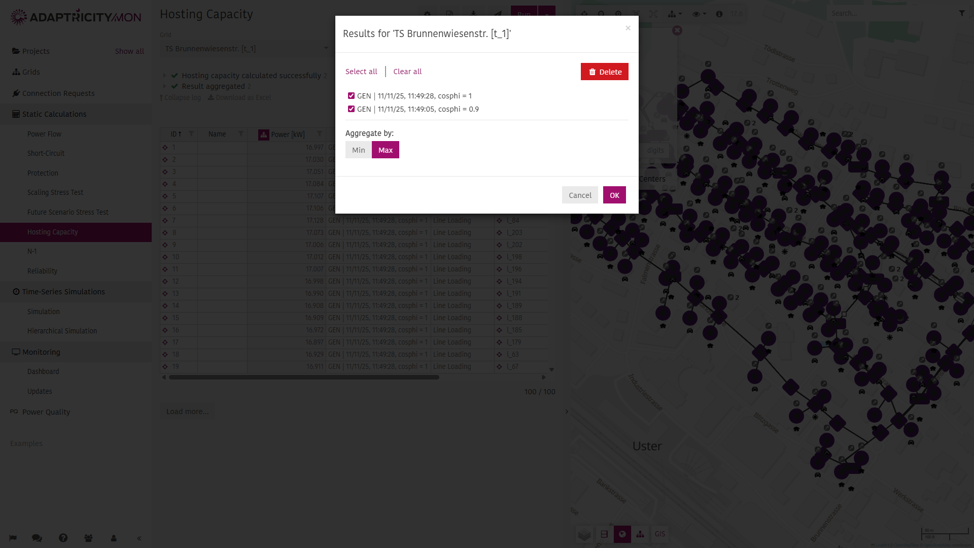
The selected results can be aggregated by minimum or maximum hosting capacity. Clicking will updated the Results Table showing the minimum or maximum hosting capacity among all selected results and a new column Result from indicating the result's origin.
Grid Viewer
The grid viewer will color the buses based on the selection in the Results Table. A standard color scale will be applied. The scale can be edited by clicking the icon next to the variable name. Clicking on will show the results next to the buses.
Clicking on a bus in the grid viewer reveals the Hosting Capacity results for that bus on the right.